
-
Engineering and Architecture
Exams
Colleges
Predictors
Resources
-
Computer Application and IT
Quick Links
Colleges
-
Pharmacy
Colleges
Resources
-
Hospitality and Tourism
Colleges
Resources
Diploma Colleges
-
Competition
Other Exams
Resources
-
School
Exams
Top Schools
Products & Resources
-
Study Abroad
Top Countries
Resources
-
Arts, Commerce & Sciences
Colleges
Upcoming Events
Resources
-
Management and Business Administration
Exams
Colleges & Courses
Predictors
-
Learn
Law Preparation
MBA Preparation
Engineering Preparation
Medical Preparation
-
Online Courses and Certifications
Top Streams
Specializations
- Digital Marketing Certification Courses
- Cyber Security Certification Courses
- Artificial Intelligence Certification Courses
- Business Analytics Certification Courses
- Data Science Certification Courses
- Cloud Computing Certification Courses
- Machine Learning Certification Courses
- View All Certification Courses
Resources
-
Medicine and Allied Sciences
Colleges
Predictors
Resources
-
Law
Resources
Colleges
-
Animation and Design
Exams
Predictors & Articles
Colleges
Resources
-
Media, Mass Communication and Journalism
Colleges
Resources
-
Finance & Accounts
Top Courses & Careers
Colleges
Get Answers to all your Questions


Q. 14.14 Write the truth table for the circuit given in Fig. 14.39 below consisting of NOR gates and identify the logic operation (OR, AND, NOT) that this circuit is performing.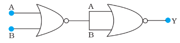
(Hint: then
and in the end puts of second NOR gate will be
and hence
Similarly work out the values of
for other combinations of
and
Compare with the truth table of OR, AND, NOT gates and find the correct one.)
Answers (1)

A and B are the input of a NOR gate and the Output of this NOR gate is the Input of another NOR gate whose Output is Y. Hence,
Y =
Y = .
Y = A + B
Hence Circuit behaves as an OR gate.
Truth table
| INPUTS | OUTPUT |
| 00 | 0 |
| 01 | 1 |
| 10 | 1 |
| 11 | 1 |
Crack CUET with india's "Best Teachers"
- HD Video Lectures
- Unlimited Mock Tests
- Faculty Support

Similar Questions
- 100 g of liquid A (molar mass 140 g mol^-1) was dissolved in 1000 g of liquid B (molar mass 180 g mol^-1).The vapour pressure of pure liquid B was found to be 500 torr.
- 100 turn rectangular coil ABCD (in X-Y plane) is hung from one arm of a balance (shown in figure). A mass 500 g is added to the other arm to balance the weight of the coil.
- 100m long antenna is mounted on a 500m tall building The complex can become a transmission tower for waves with λ (a) ~ 400 m (b) ~ 25 m (c) ~ 150 m (d) ~ 2400 m

