Apply to Aakash iACST Scholarship Test 2024
Search Colleges, Exams, Schools & more
NCERT Solutions for Class 12 Physics Chapter 7 Alternating Current
Edited By Vishal kumar | Updated on Sep 09, 2023 02:53 PM IST | #CBSE Class 12th
NCERT Solutions for Class 12 Physics Chapter 7 – Access and Download Free PDF
NCERT Solutions for Class 12 Physics Chapter 7 Alternating current is a crucial and scoring chapter in the Class 12 syllabus. This NCERT solution page offers detailed step-by-step solutions prepared by physics experts from Careers360. It covers a total of twenty-six questions, including those from 7.1 to 7.11 in the exercise section and the remaining in the additional exercise section.
This Story also Contains
- NCERT Solutions for Class 12 Physics Chapter 7 – Access and Download Free PDF
- NCERT Solutions for Class 12 Physics Chapter 7 Alternating Current
- Class 12 Physics Chapter 7 Exercise Solutions
- NCERT Class 12 Physics Chapter 7 Exercise Solutions: Additional Exercise
- NCERT Solutions for class 12 physics: Chapter-Wise
- NCERT Class 12 Physics Chapter 7 Alternating Current: Important topics
- Key Features of Class 12 Physics NCERT Solutions for Chapter 7 Alternating Current
- Also Check NCERT Books and NCERT Syllabus here:
The supply that is received in our home is alternating in nature. Do you know what is the value of the normal supply voltage that is coming into our home and what is the supply frequency? Alternating Current Class 12 chapter will help you to clear such doubts. NCERT questions explained in CBSE NCERT solutions for Class 12 physics chapter 7 are based on the single-phase alternating current.
Alternating Current Class 12 NCERT solutions are the basics for the topics needed to study for CBSE board exam. Students should go through the Alternating Current NCERT solutions to know the answer to the question of Alternating current. In this class 12 physics chapter 7 exercise solutions you will study the concept of phasor diagrams and related problems.
Free download ncert class 12 physics chapter 7 exercise solutions PDF for CBSE exam.
NCERT Solutions for Class 12 Physics Chapter 7 Alternating Current
Class 12 Physics Chapter 7 Exercise Solutions
Q7.1 (a) A resistor is connected to a
,
ac supply.
a)what is the RMS value of current?
Answer:
Given,
RMS voltage in the circuit
Resistance in the circuit
Now,
RMS current in the circuit:
Hence, the RMS value of current is 2.2A.
Q7.1 (b) A resistor is connected to a
,
ac supply.
What is the rms value of current in the circuit?
Answer:
Given,
RMS Voltage in the circuit
Resistance in the circuit
Now,
RMS Current in the circuit:
Hence, the RMS value of current is 2.2A.
Q7.1 (c) A resistor is connected to a
,
ac supply.
What is the net power consumed over a full cycle?
Answer:
Given,
Supplied RMS Voltage
Supplied RMS Current
The net power consumed over a full cycle:
Hence net power consumed is 484W.
Q7.2 (a) The peak voltage of an ac supply is . What is the RMS voltage?
Answer:
Given
Peak Value of ac supply:
Now as we know in any sinusoidal function
Since our ac voltage supply is also sinusoidal
Hence RMS value of voltage os 212.13V.
Q7.2 (b) The RMS value of current in an ac circuit is . What is the peak current?
Answer:
Given,
RMS value of current
Since Current is also sinusoidal (because only resistance is present in the circuit, not the capacitor and inductor)
Hence the peak value of current is 14.1A.
Q7.3 A inductor is connected to
,
ac supply. Determine the RMS value of the current in the circuit.
Answer:
Given
Supply Voltage
Supply Frequency
The inductance of the inductor connected
Now
Inductive Reactance
RMS Value of the current :
Hence the RMS Value of current is 15.92A.
Q7.4 A capacitor is connected to a
,
ac supply. Determine the rms value of the current in the circuit.
Answer:
Given,
Supply Voltage
Supply Frequency
The capacitance of the connected capacitor
Now,
Capacitive Reactance
RMS Value of current
Hence the RMS Value of current is 2.49A.
Answer:
As we know,
Power absorbed
Where is the phase difference between voltage and current.
for the inductive circuit is -90 degree and
for the capacitive circuit is +90 degree.
In both cases (inductive and capacitive), the power absorbed by the circuit is zero because in both cases the phase difference between current and voltage is 90 degree.
This can be seen as The elements(Inductor and Capacitor) are not absorbing the power, rather storing it. The capacitor is storing energy in electrostatic form and Inductor is storing the energy in magnetic form.
Q7.6 Obtain the resonant frequency of a series
circuit with
,
and
. What is the Q -value of this circuit?
Answer:
Given, in a circuit,
Inductance,
Capacitance,
Resistance,
Now,
Resonance frequency (frequency of maximum current OR minimum impedance OR frequency at which inductive reactance cancels out capacitive reactance )
Hence Resonance frequency is 125 per second.
Q-Value:
Hence Q - value of the circuit is 25.
Answer:
Given
Capacitance
Inductance
Now,
Angular Frequency
Hence Angular Frequency is
Answer:
Given
Capacitance
Inductance
Charge on the capacitor
Now,
The total energy stored in Capacitor :
Total energy later will be same because energy is being shared with capacitor and inductor and none of them loses the energy, they just store it and transfer it.
Answer:
Given,
Resistance
Inductance
Capacitance
Voltage supply
At resonance, supply frequency is equal to the natural frequency, and at the natural frequency, the total impedance of the circuit is equal to the resistance of the circuit
as inductive and capacitive reactance cancels each other. in other words,
As
Now,
Current in the circuit
Average Power transferred in the circuit :
Hence average power transferred is 2000W.
Answer:
Given,
Range of the frequency in which radio can be tune =
The effective inductance of the Circuit =
Now, As we know,
where is tuning frequency.
For getting the range of the value of a capacitor, let's calculate the two values of the capacitor, one maximum, and one minimum.
first, let's calculate the minimum value of capacitance which is the case when tuning frequency = 800KHz.
Hence the minimum value of capacitance is 198pF.
Now, Let's calculate the maximum value of the capacitor.
in this case, tuning frequency = 1200KHz
Hence the maximum value of the capacitor is 88.04pf
Hence the Range of the values of the capacitor is .
Q7.11 (a) Figure shows a series LCR circuit connected to a variable frequency source.
,
,
.
(a) Determine the source frequency which drives the circuit in resonance.
Answer:
Given,
Variable frequency supply voltage = 230V
Inductance
Capacitance
Resistance
a) Resonance angular frequency in this circuit is given by :
Hence this circuit will be in resonance when supply frequency is 50 rad/sec.
Q7.11 (b) Figure shows a series LCR circuit connected to a variable frequency source.
(b) Obtain the impedance of the circuit and the amplitude of current at the resonating frequency.

Answer:
Given,
Variable frequency supply voltage = 230V
Inductance
Capacitance
Resistance
Now,
The impedance of the circuit is
at Resonance Condition
:
Hence, Impedance at resonance is 40 .
Now, at resonance condition, impedance is minimum which means current is maximum which will happen when we have a peak voltage, so
Current in the Resonance circuit is Given by
Hence amplitude of the current at resonance is 8.13A.
Q7.11 Figure shows a series LCR circuit connected to a variable frequency source.

Answer:
Potential difference across any element =
Now
The potential difference across the capacitor:
The potential difference across the inductor
The potential difference across Resistor
=40 Irms=230V
The potential difference across LC combination
Hence at resonating, frequency potential difference across LC combination is zero.
NCERT Class 12 Physics Chapter 7 Exercise Solutions: Additional Exercise
What is the total energy stored initially? Is it conserved during oscillations?
Answer :
Given,
The inductance of the inductor:
The capacitance of the capacitor :
The initial charge on the capacitor:
Total energy present at the initial moment:
Hence initial energy in the circuit is 1J. Since we don't have any power-consuming element like resistance in the circuit, the energy will be conserved
What is the natural frequency of the circuit?
Answer:
Given,
The inductance of the inductor:
The capacitance of the capacitor :
The initial charge on the capacitor:
The natural angular frequency of the circuit:
Hence the natural angular frequency of the circuit is .
The natural frequency of the circuit:
Hence the natural frequency of the circuit is 159Hz.
Q7.12 (c-i) An circuit contains a
inductor and a
capacitor with an initial charge of
. The resistance of the circuit is negligible. Let the instant the circuit is closed be
.
( c) At what time is the energy stored
(i) completely electrical (i.e., stored in the capacitor)?
Answer:
at any instant, the charge on the capacitor is:
Where time period :
Now, when the total energy is purely electrical, we can say that
this is possible when
Hence Total energy will be purely electrical(stored in a capacitor) at
.
Q7.12 (c-ii) An circuit contains a
inductor and a
capacitor with an initial charge of
. The resistance of the circuit is negligible.
(C) Let the instant the circuit is closed be .
(ii) completely magnetic (i.e., stored in the inductor)?
Answer:
The stored energy will we purely magnetic when the pure electrical stored is zero. i.e. when the charge on the capacitor is zero, all energy will be stored in the inductor.
So, t for which charge on the capacitor is zero is
Hence at these times, the total energy will be purely magnetic.
Q7.12 (d) An circuit contains a
inductor and a
capacitor with an initial charge of
. The resistance of the circuit is negligible. Let the instant the circuit is closed be
.
At what times is the total energy shared equally between the inductor and the capacitor?
Answer:
The energy will be shared equally when the energy in the capacitor is half of the maximum energy it can store.i.e.
From here, we got
So now, we know the charge on the capacitor, we can calculate the time for which
From here,
Hence for these times, the total energy will be shared equally between capacitor and inductor.
If a resistor is inserted in the circuit, how much energy is eventually dissipated as heat?
Answer:
If the resistance is added to the circuit, the whole energy will dissipate as heat eventually. energy will keep moving between the capacitor and inductor with reducing in magnitude in each cycle and eventually all energy will be dissipated.
Answer:
Given,
The inductance of the coil
the resistance of the coil
Supply voltage
Supply voltage frequency
Now, as we know peak voltage = (RMS Voltage)
Peak voltage
The impedance of the circuit :
Now peak current in the circuit :
Hence peak current is 1.82A in the circuit.
Answer:
Let the voltage in the circuit be
and
Current in the circuit be
Where is the phase difference between voltage and current.
V is maximum At
t = 0
is maximum At
Hence, the time lag between voltage maximum and the current maximum is
.
For phase difference we have
Hence time lag between the maximum voltage and the maximum current is
Answer:
Given,
The inductance of the coil
the resistance of the coil
Supply voltage
Supply voltage frequency
a)
Now, as we know peak voltage = (RMS Voltage)
Peak voltage
Now,
The impedance of the circuit :
Now peak current in the circuit :
Hence peak current is in the circuit.
The current in the circuit is very small, which is one of the indications of inductor working as a nearly open circuit in the case of high frequency.
b)
For phase difference we have
Now
Hence time lag between the maximum voltage and the maximum current is .
In the DC circuit, after attaining the steady state, inductor behaves line short circuit as is Zero.
Answer:
Given,
The capacitance of the capacitor
The resistance of the circuit
Voltage supply
Frequency of voltage supply
The maximum current in the circuit
Hence maximum current in the circuit is 3.24A.
Answer:
In the case of a capacitor, we have
So,
So the time lag between max voltage and the max current is :
Answer:
Given,
The capacitance of the capacitor
The resistance of the circuit
Voltage supply
Frequency of voltage supply
The maximum current in the circuit
Hence maximum current in the circuit is 3.9A.
b)
In the case of capacitor, we have
So,
So the time lag between max voltage and max current is :
At high frequencies, tends to zero. which indicates capacitor acts as a conductor at high frequencies.
In the DC circuit, after a steady state is achieved, Capacitor acts like an open circuit.
Answer:
As we know, in the case of a parallel RLC circuit:
The current will be minimum when
Which is also the condition of natural frequency. Hence the total current is minimum when source frequency is equal to the natural frequency.
RMS value of current in R
RMS value in Inductor
RMS value in capacitor
Capacitor current and inductor current will cancel out each other so the current flowing in the circuit is 5.75A.
Answer:
The inductance of the inductor
The capacitance of the capacitor
Voltage supply
Frequency of voltage supply .
Here, we have
Impedance
Now,
Current in the circuit will be
where,
The negative sign is just a matter of the direction of current.so,
here
But, since the value of R is zero(since our circuit have only L and C)
Hence
Now,
RMS value of this current:
.
Answer:
As we know,
RMS potential drop across an element with impedance Z:
SO,
RMS potential difference across inductor:
RMS potential drop across capacitor
Q7.18 (c) A circuit containing a inductor and a
capacitor in series is connected to a
,
supply. The resistance of the circuit is negligible
(c) What is the average power transferred to the inductor?
Answer:
Since
Current flowing in the circuit is sinusoidal and hence average power will be zero as the average of sin function is zero.in other words, the inductor will store energy in the positive half cycle of the sin (0 degrees to 180 degrees) and will release that energy in the negative half cycle(180 degrees to 360 degrees), and hence average power is zero.
Answer:
As we know,
Average power where
is the phase difference between voltage and current.
Since in the circuit, phase difference is
, the average power is zero.
Answer:
Since the phase difference between voltage and current is 90 degree, even the total power absorbed by the circuit is zero. This is an ideal circuit, we can not have any circuit in practical that consumes no power, that is because practically resistance of any circuit is never zero. Here only inductor and capacitor are present and none of them consumes energy, they just store it and transfer it like they are doing it in this case.
Q7.19 Suppose the circuit in Exercise 7.18 has a resistance of . Obtain the average power transferred to each element of the circuit, and the total power absorbed.
Answer:
The inductance of the inductor
The capacitance of the capacitor
The resistance of a resistor
Voltage supply
Frequency of voltage supply
As we know,
Impedance
Current flowing in the circuit :
Now,
Average power transferred to the resistor:
Average power transferred to the inductor = 0
Average power transferred to the capacitor = 0:
Total power absorbed by circuit :
Hence circuit absorbs 788.44W.
Q7.20 (a) A series LCR circuit with ,
,
is connected to a
variable frequency supply.
What is the source frequency for which current amplitude is maximum. Obtain this maximum value.
Answer:
The inductance of the inductor
The capacitance of the capacitor
The resistance of the resistor
Voltage supply
Frequency of voltage supply
As we know,
the current amplitude is maximum at the natural frequency of oscillation, which is
Also, at this frequency,
SO,
The maximum current in the circuit :
Hence maximum current is 14.14A.
Q7.20 (b) A series LCR circuit with ,
,
is connected to a
variable frequency supply.
Answer:
Since the resistor is the only element in the circuit which consumes the power, the maximum absorbed power by circuit will be maximum when power absorbed by the resistor will be maximum. power absorbed by the resistor will be maximum at when current is maximum which is the natural frequency case,
Hence when source frequency will be equal to the natural frequency, the power absorbed will be maximum.
Hence frequency
Maximum Power Absorbed
.
Answer:
The value of maximum angular frequency is calculated in the first part of the question and whose magnitude is 4166.67
Q-factor of any circuit is given by
Hence Q-factor for the circuit is 21.74.
Answer:
As
Power
Power will be half when the current
is
times the maximum current.
As,
At half powerpoint :
here,
On putting values, we get, two values of for which
And they are:
Also,
The current amplitude at these frequencies
Q7.21 Obtain the resonant frequency and -factor of a series
circuit with
,
, and
. It is desired to improve the sharpness of the resonance of the circuit by reducing its ‘full width at half maximum’ by a factor of 2. Suggest a suitable way.
Answer:
The inductance of the inductor
The capacitance of the capacitor
The resistance of the resistor
Now,
Resonant frequency
Q-Factor of the circuit
Now, to improve the sharpness of resonance by reducing its full width at half maximum, by a factor of 2 without changing ,
we have to change the resistance of the resistor to half of its value, that is
Answer:
Yes, at any instant the applied voltage will be distributed among all element and the sum of the instantaneous voltage of all elements will be equal to the applied. But this is not the case in RMS because all elements are varying differently and they may not be in the phase.
7.22 (b) Answer the following questions: A capacitor is used in the primary circuit of an induction coil.
Answer:
Yes, we use capacitors in the primary circuit of an induction coil to avoid sparking. when the circuit breaks, a large emf is induced and the capacitor gets charged from this avoiding the case of sparking and short circuit.
Q 7.22 (c) Answer the following questions:
An applied voltage signal consists of a superposition of a voltage and an ac voltage of high frequency. The circuit consists of an inductor and a capacitor in series. Show that the dc signal will appear across
and the ac signal across
.
Answer:
For a high frequency, the inductive reactance and capacitive reactance:
Hence the capacitor does not offer resistance to a higher frequency, so the ac voltage appears across L.
Similarly
For DC, the inductive reactance and capacitive reactance:
Hence DC signal appears across Capacitor only.
Q 7.22 (d) Answer the following questions:
A choke coil in series with a lamp is connected to a dc line. The lamp is seen to shine brightly. Insertion of an iron core in the choke causes no change in the lamp’s brightness. Predict the corresponding observations if the connection is to an ac line.
Answer:
For a steady state DC, the increasing inductance value by inserting iron core in the choke, have no effect in the brightness of the connected lamp, whereas, for ac when the iron core is inserted, the light of the lamp will shine less brightly because of increase in inductive impedance.
Q7.22 (e) Answer the following questions:
Why is choke coil needed in the use of fluorescent tubes with ac mains? Why can we not use an ordinary resistor instead of the choke coil?
Answer:
We need choke coil in the use of fluorescent tubes with ac mains to reduce the voltage across the tube without wasting much power. If we use simply resistor for this purpose, there will be more power loss, hence we do not prefer it.
Answer:
Given,
Input voltage:
Number of turns in the primary coil
Output voltage:
Now,
Let the number of turns in secondary be
Now as we know, in a transformer,
Hence the number of turns in secondary winding id 400.
Q7.24 At a hydroelectric power plant, the water pressure head is at a height of and the water flow available is
. If the turbine generator efficiency is
, estimate the electric power availablefrom the plant
.
Answer:
Given,
Height of the water pressure head
The volume of the water flow per second
Turbine generator efficiency
Mass of water flowing per second
The potential energy stored in the fall for 1 second
Hence input power
Now as we know,
Hence output power is 176.4 MW.
Answer:
Power required
The total resistance of the two-wire line
Input Voltage
Output Voltage:
RMS Current in the wireline
Now,
Power loss in the line
Hence, power loss in line is 600kW.
How much power must the plant supply, assuming there is negligible power loss due to leakage?
Answer:
Power required
The total resistance of the two-wire line
Input voltage
Output voltage:
RMS current in the wireline
Now,
Total power delivered by plant = line power loss + required electric power = 800 + 600 = 1400kW.
Answer:
Power required
The total resistance of the two-wire line
Input Voltage
Output Voltage:
RMS Current in the wireline
Now,
Voltage drop in the power line =
Total voltage transmitted from the plant = 3000+4000=7000
as power is generated at 440V, The rating of the power plant is 440V-7000V.
Q7.26 Do the same exercise as above with the replacement of the earlier transformer by a step-down transformer (Neglect, as before, leakage losses though this may not be a good assumption any longer because of the very high voltage transmission involved). Hence, explain why high voltage transmission is preferred?
Answer:
Power required
The total resistance of the two-wire line
Input Voltage
Output Voltage:
RMS current in the wireline
Now,
a) power loss in the line
b)
Power supplied by plant = 800 kW + 6 kW = 806kW.
c)
Voltage drop in the power line =
Total voltage transmitted from the plant = 300+40000=40300
as power is generated at 440V, The rating of the power plant is 440V-40300V.
We prefer high voltage transmission because power loss is a lot lesser than low voltage transmission.
NCERT Solutions for class 12 physics: Chapter-Wise
Here are the exercise-wise solutions of the NCERT Class 12 physics book:
Alternating current class 12 solutions: Important Formulas and Diagrams
Important Formulas and Diagrams serve as a crucial resource for exam preparation, be it for board exams or competitive ones like JEE and NEET. These formulas and diagrams condense complex concepts, aiding students in quick revision and problem-solving, ultimately boosting their confidence and performance in exams.
Alternating Current and Voltage
JEE Main Highest Scoring Chapters & Topics
Just Study 40% Syllabus and Score upto 100%
Download EBookI=Iosinωt Alternating current
V=Vosinωt Alternating Voltage
Where: Io is the peak value of current and Vo is the peak value of voltage
Periodic Time:

Frequency(f):

Mean Value of An Alternating Current:

Impedance and Resistance
For L-R series circuit: 
For R-C series circuit: 
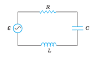
Series LRC Circuit
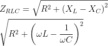
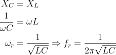
At resonant frequency,
Voltage and power in a transformer
The voltage across secondary coil: ![]()
Input and Output power: ![]()
NCERT Class 12 Physics Chapter 7 Alternating Current: Important topics
Class 12 NCERT introduces the concept of different ac circuits including the elements, resistor, capacitor, inductor and ac voltage source. Single-phase ac circuits and their questions are discussed in the NCERT Solutions for Class 12 physics chapter 7. The following are the main headings covered in physics Class 12 chapter 7.
AC voltage applied to a resistor- In this section, the analysis of a resistor circuit applied with an ac voltage of Vmsinωt is done and the terms like RMS and peak voltage and current is introduced. Also, the power dissipated in the resistor circuit is discussed. Question 1 and 2 of chapter 7 Physics Class 12 NCERT solutions given are based on this topic. The main formulas used here are:
![]()
The power consumed in a resistor circuit connected with ac source, P= Vrms * Irms
In the next part of Alternating Current class 12, phasor representation of voltage and current is introduced.
Ch 7 physics Class 12 gives a small analysis of circuits involving R, L and C. Alternating Current Class 12 NCERT pdf solutions discuss questions based on series RL, RC and RLC circuits. Also, chapter 7 Class 12 physics discuss circuit including capacitance and inductance only
The concepts of LC oscillation, resonance and transformer and their basic equations are discussed.
Key Features of Class 12 Physics NCERT Solutions for Chapter 7 Alternating Current
omprehensive Coverage: These ncert class 12 physics chapter 7 exercise solutions encompass all topics and questions presented in Chapter 7, ensuring a thorough understanding of alternating current.
Detailed Explanations: Each ac current class 12 solution offers in-depth explanations, helping students grasp complex concepts.
Clarity and Simplicity: The alternating current class 12 solutions are presented in clear and straightforward language, making it easier for students to comprehend.
Practice Questions: Exercise questions are included for students to practice and assess their understanding.
Exam Preparation: These physics chapter 7 class 12 solutions are instrumental in board exam preparation and provide valuable support for competitive exams like JEE and NEET.
Foundation for Advanced Study: The concepts covered in this chapter are foundational for advanced physics and electrical engineering studies.
Free Accessibility: These alternating current questions and answers pdf are available for free, ensuring accessibility to all students.
These features make Alternating Current Class 12 NCERT solutions a valuable tool for students, facilitating their success in exams and future studies.
Also Check NCERT Books and NCERT Syllabus here:
- NCERT Books Class 12 Physics
- NCERT Syllabus Class 12 Physics
- NCERT Books Class 12
- NCERT Syllabus Class 12
NCERT solutions subject wise
- NCERT solutions for class 12 mathematics
- NCERT solutions for class 12 chemistry
- NCERT solutions for class 12 physics
- NCERT solutions for class 12 biology
Significance of NCERT solutions for class 12 physics chapter 7 in board exam
From the unit electromagnetic induction and alternating current Class 12, around 10% of the questions are asked in the CBSE 12th board exam.
If all the Class 12 Physics Chapter 7 NCERT solutions are covered then it is easy to answer questions asked in board exams.
This chapter 7 of NCERT Class 12 physics solutions is also important for JEE Main, NEET, state board exams, and competitive exams.
Prepare the chapter well with the help of CBSE NCERT Class 12 Physics Chapter 7 solutions.
Also, check
Frequently Asked Question (FAQs)
1. Is the supply coming to our home alternating?
Yes, the supply received in our home is alternating. Usually, domestic supplies are single-phase and supply to industries, factories etc are three-phase.
2. What type of questions are asked in board exams from the chapter alternating current?
In the previous year question papers, questions related to identifying the circuit elements are repeatedly asked. Along with this simple numerical questions are also asked from Alternating Current. For practising numerical, solve NCERT exercise questions, NCERT exemplar questions and previous year papers.
3. What is the weightage of chapter for JEE Main?
One question for JEE main can be expected from the Class 12 chapter Alternating Current.
4. How important is the chapter for NEET?
One or two questions may be asked from NCERT chapter Alternating Current for NEET exam.
5. What is the difference between alternating current(AC) and direct current(DC)?
AC and DC are two types of electrical current that differ in the direction of electron flow. AC periodically changes direction while DC flows in only one direction. AC is commonly used for power transmission over long distances, while DC is used for electronic devices that require constant voltage or current. AC generators are simpler and cheaper to build than DC generators.
Also Read
Articles
Certifications By Top Providers
Artificial Intelligence Projects
Via Great Learning Introduction to Watson AI
Via IBM Full-Stack Web Development
Via Masai School Introduction to Data Science
Via IBM Digital Banking Business Model
Via State Bank of India Edx
1111 coursesCoursera
788 coursesUdemy
327 coursesFuturelearn
141 coursesHarvard University, Cambridge
98 coursesIBM
85 coursesExplore Top Universities Across Globe
University of Essex, Colchester
Wivenhoe Park Colchester CO4 3SQUniversity College London, London
Gower Street, London, WC1E 6BTThe University of Edinburgh, Edinburgh
Old College, South Bridge, Edinburgh, Post Code EH8 9YLUniversity of Bristol, Bristol
Beacon House, Queens Road, Bristol, BS8 1QUUniversity of Nottingham, Nottingham
University Park, Nottingham NG7 2RDLancaster University, Lancaster
Bailrigg, Lancaster LA1 4YWTop Universities in Australia for International Students 2024 - QS Ranking
11 min ⋆ May 02, 2024 12:05 PM ISTSAT Exam Fees 2024 - Registration, Late, Cancellation, Score Services Fee
4 min ⋆ Mar 11, 2024 07:03 AM ISTSAT Sample Papers 2024 - Question Papers PDF for SAT Practice Test
7 min ⋆ May 02, 2024 11:05 AM ISTTop Universities in Canada for International Students 2024 - QS Ranking
9 min ⋆ May 02, 2024 10:05 AM ISTStudy MBBS in USA for Indian and International Students 2024
14 min ⋆ Feb 01, 2024 04:02 AM ISTHow to Apply for Eligibility Certificate for Studying MBBS Abroad?
6 min ⋆ May 02, 2024 09:05 AM ISTQuestions related to CBSE Class 12th
Have a question related to CBSE Class 12th ?
Here are some options you can explore to get admission in a good school even though admissions might be closed for many:
-
Waitlist: Many schools maintain waitlists after their initial application rounds close. If a student who secured a seat decides not to join, the school might reach out to students on the waitlist. So, even if the application deadline has passed, it might be worth inquiring with schools you're interested in if they have a waitlist and if they would consider adding you to it.
-
Schools with ongoing admissions: Some schools, due to transfers or other reasons, might still have seats available even after the main admission rush. Reach out to the schools directly to see if they have any open seats in 10th grade.
-
Consider other good schools: There might be other schools in your area that have a good reputation but weren't on your initial list. Research these schools and see if they have any seats available.
-
Focus on excelling in your current school: If you can't find a new school this year, focus on doing well in your current school. Maintain good grades and get involved in extracurricular activities. This will strengthen your application for next year if you decide to try transferring again.
Best CBSE schools in Delhi: Click Here
Garima Sihag 06 May,2024
In India, the design and coding fields offer exciting career options that can leverage your interest in both. Here's how you can navigate this path:
Choosing Your Stream:
-
Graphic Design Focus: Consider a Bachelor's degree in Graphic Design or a design diploma. Build a strong portfolio showcasing your creative skills. Learn the basics of HTML, CSS, and JavaScript to understand web development better. Many online resources and bootcamps offer these introductory courses.
-
Coding Focus: Pursue a Computer Science degree or a coding bootcamp in India. These programs are intensive but can equip you with strong coding skills quickly. While building your coding prowess, take online courses in graphic design principles and UI/UX design.
Engineering Subjects (for a Degree):
-
Information Technology (IT): This offers a good mix of web development, networking, and database management, all valuable for web design/development roles.
-
Human-Computer Interaction (HCI): This is a specialized field that bridges the gap between design and computer science, focusing on how users interact with technology. It's a perfect choice if you're interested in both aspects.
Garima Sihag 07 May,2024
- Passing NIOS in October 2024 will make you eligible for NIT admissions in 2025 . NIT admissions are based on your performance in entrance exams like JEE Main, which typically happen in January and April. These exams consider the previous year's Class 12th board results (or equivalent exams like NIOS).
Here's why 2025 is more likely:
- JEE Main 2024 Admissions: The application process for NITs through JEE Main 2024 is likely complete by now (May 2024). They consider your 2023 Class 12th marks (CBSE in this case).
- NIOS Results: Since NIOS results typically come out after the NIT admission process, your October 2024 NIOS marks wouldn't be available for JEE Main 2024.
Looking Ahead (2025 Admissions):
- Focus on JEE Main: Since you have a computer science background, focus on preparing for JEE Main 2025. This exam tests your knowledge in Physics, Chemistry, and Mathematics, crucial for engineering programs at NITs.
- NIOS Preparation: Utilize the time between now and October 2024 to prepare for your NIOS exams.
- Eligibility Criteria: Remember, NITs typically require a minimum of 75% marks in Class 12th (or equivalent) for general category students (65% for SC/ST). Ensure you meet this criteria in your NIOS exams.
Garima Sihag 07 May,2024
Yes, scoring above 99.9 percentile in CAT significantly increases your chances of getting a call from IIM Bangalore, with your academic background. Here's why:
-
High CAT Score: A score exceeding 99.9 percentile is exceptional and puts you amongst the top candidates vying for admission. IIM Bangalore prioritizes CAT scores heavily in the shortlisting process.
-
Strong Academics: Your 96% in CBSE 12th and a B.Tech degree demonstrate a solid academic foundation, which IIM Bangalore also considers during shortlisting.
However, the shortlisting process is multifaceted:
- Other Factors: IIM Bangalore considers other factors beyond CAT scores, such as your work experience (if any), XAT score (if you appear for it), academic diversity, gender diversity, and performance in the interview and Written Ability Test (WAT) stages (if shortlisted).
Here's what you can do to strengthen your application:
-
Focus on WAT and PI: If you receive a shortlist, prepare extensively for the Written Ability Test (WAT) and Personal Interview (PI). These stages assess your communication, soft skills, leadership potential, and suitability for the program.
-
Work Experience (if applicable): If you have work experience, highlight your achievements and how they align with your chosen IIM Bangalore program.
Overall, with a stellar CAT score and a strong academic background, you have a very good chance of getting a call from IIM Bangalore. But remember to prepare comprehensively for the other stages of the selection process.
Garima Sihag 07 May,2024
hello,
Yes you can appear for the compartment paper again since CBSE gives three chances to a candidate to clear his/her exams so you still have two more attempts. However, you can appear for your improvement paper for all subjects but you cannot appear for the ones in which you have failed.
I hope this was helpful!
Good Luck
Upasana Barman 24 August,2022
Popular CBSE Class 12th Questions
A block of mass 0.50 kg is moving with a speed of 2.00 ms-1 on a smooth surface. It strikes another mass of 1.00 kg and then they move together as a single body. The energy loss during the collision is
| Option 1)
|
Option 2)
|
| Option 3)
|
Option 4)
|
An athlete in the olympic games covers a distance of 100 m in 10 s. His kinetic energy can be estimated to be in the range
| Option 1)
|
Option 2)
|
| Option 3)
|
Option 4)
|
A particle is projected at 600 to the horizontal with a kinetic energy . The kinetic energy at the highest point
| Option 1)
|
Option 2)
|
| Option 3)
|
Option 4)
|
In the reaction,
| Option 1)
|
Option 2)
|
| Option 3)
|
Option 4)
|
How many moles of magnesium phosphate, will contain 0.25 mole of oxygen atoms?
| Option 1)
0.02 |
Option 2)
3.125 × 10⁻² |
| Option 3)
1.25 × 10⁻² |
Option 4)
2.5 × 10⁻² |
Colleges After 12th
Also Read
Applications for Admissions are open.

JEE Main Important Physics formulas
ApplyAs per latest 2024 syllabus. Physics formulas, equations, & laws of class 11 & 12th chapters
Aakash iACST Scholarship Test 2024
ApplyGet up to 90% scholarship on NEET, JEE & Foundation courses

JEE Main Important Chemistry formulas
ApplyAs per latest 2024 syllabus. Chemistry formulas, equations, & laws of class 11 & 12th chapters
PACE IIT & Medical, Financial District, Hyd
ApplyEnrol in PACE IIT & Medical, Financial District, Hyd for JEE/NEET preparation
ALLEN JEE Exam Prep
ApplyStart your JEE preparation with ALLEN
ALLEN NEET Coaching
ApplyAce your NEET preparation with ALLEN Online Programs
News and Notifications
March 22, 2024 - 08:10 PM IST :
February 02, 2024 - 03:48 PM IST :
January 04, 2024 - 06:06 PM IST :
May 01, 2024 - 03:34 PM IST
April 26, 2024 - 07:45 PM IST
April 04, 2024 - 03:43 PM IST
April 02, 2024 - 04:40 PM IST
March 23, 2024 - 05:04 PM IST
March 19, 2024 - 07:54 AM IST
March 18, 2024 - 05:29 PM IST
Stay up-to date with CBSE Class 12th News
Download Careers360 App's
Regular exam updates, QnA, Predictors, College Applications & E-books now on your Mobile

300M+
Students

36,000+
Colleges

550+
Exams

1500+
E-Books

16000+
Certifications

We Appeared in
Back to top