
-
Engineering and Architecture
Exams
Colleges
Predictors
Resources
-
Computer Application and IT
Quick Links
Colleges
-
Pharmacy
Colleges
Resources
-
Hospitality and Tourism
Colleges
Resources
Diploma Colleges
-
Competition
Other Exams
Resources
-
School
Exams
Top Schools
Products & Resources
-
Study Abroad
Top Countries
Resources
-
Arts, Commerce & Sciences
Exams
Colleges
Upcoming Events
Resources
-
Management and Business Administration
Colleges & Courses
Predictors
-
Learn
Law Preparation
MBA Preparation
Engineering Preparation
Medical Preparation
-
Online Courses and Certifications
Top Streams
Specializations
- Digital Marketing Certification Courses
- Cyber Security Certification Courses
- Artificial Intelligence Certification Courses
- Business Analytics Certification Courses
- Data Science Certification Courses
- Cloud Computing Certification Courses
- Machine Learning Certification Courses
- View All Certification Courses
Resources
-
Medicine and Allied Sciences
Colleges
Predictors
Resources
-
Law
Resources
Colleges
-
Animation and Design
Exams
Predictors & Articles
Colleges
Resources
-
Media, Mass Communication and Journalism
Colleges
Resources
-
Finance & Accounts
Top Courses & Careers
Colleges
Get Answers to all your Questions


- Home
- Engineering
- In the circuit diagrams (A, B, C and D) shown below, R is high resistance and S is a resistance of the order of galvanometer resistance G. The correct circuit, corresponding to the half deflection
- #Engineering
- #Physics
- #Class 12
- #Current Electricity
- #Birla Institute of Technology & Science Admission Test
- #National Eligilibility Cum Entrance Test
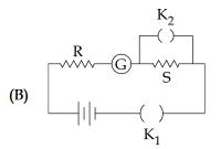
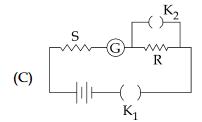
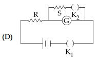
In the circuit diagrams (A, B, C and D) shown below, R is high resistance and S is a resistance of the order of galvanometer resistance G. The correct circuit, corresponding to the half deflection method for finding the resistance and figure of merit of the galvanometer, is the circuit labelled as :
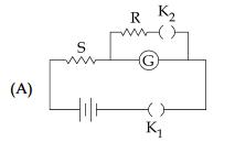
Circuit A with
Circuit B with G = S
Circuit C with G = S
Circuit D with
Answers (1)

In figure D, the current will flow through the circuit when key is closed and
is open. The current flowing through the galvanometer is proportional to the deflection in it.
where, E - emf of the cell
R- resistance from the resistance box
G- galvanometer resistance for current I
- galvanometer deflection for current I
k - proportionality constant.
When is closed and by adjusting the shunt resistance S, we can make galvanometer deflection as
.
Then the current in the circuit is :
Now, a fraction of the current I2 in the circuit flows through the galvanometer, which is given by:
Now, from the above relations, we can get the resistance of the given galvanometer as:
Similar Questions
-
5 g of Na2SO4 was dissolved in x g of H2O. The change in freezing point was found to be 3.820C. If Na2SO4 is 81.5% ionised, the value of x (K

A capacitor is made of two square plates each of side 'a' making a very small angle
-
A solution of m-chloroaniline, m-chlorophenol and m-chlorobenzoic acid in ethyl acetate was extracted initially with a saturated solution of NaHCO3 to give fraction A. The leftover organic phase was extracted with d
